HV510 High Performance Variable Frequency Drive Vector Inverter VFD Vector Frequency Converter
Variable Frequency Drive Vector Inverter Product Description
HV510 series frequency inverter is a new generation of high-performance vector inverter, which adopts new high-performance open and closed loop vector control technology to support asynchronous motor and permanent magnet synchronous motor control drive; excellent performance, enhanced performance and high power density design enhance industrial performance The product's ease of use, reliability, environmental stability, functional diversity, application flexibility and other advantages in the application environment have improved the design standards and optimized the installation space, etc., improving the user experience in many aspects.HV510 series frequency inverter is a new generation of high-performance vector inverter, which adopts new high-performance open and closed loop vector control technology to support asynchronous motor and permanent magnet synchronous motor control drive; excellent performance, enhanced performance and high power density design enhance industrial performance The product's ease of use, reliability, environmental stability, functional diversity, application flexibility and other advantages in the application environment have improved the design standards and optimized the installation space, etc., improving the user experience in many aspects.
HV510 series frequency inverters are widely used in driving various automated production equipment such as metallurgy, lifting, petroleum, machine tools, plastics, metal products, paper-making, textiles, printing and packaging, etc.
Variable Frequency Drive Vector Inverter Technical Specification
| Technical Specification |
| Power
input/output | Input voltage (Uin) | 380V (-15%) - 480V (+10%), three-phase |
| Input power
frequency | (50Hz/60Hz)±5% |
| Input voltage
imbalance | ≤3% |
| Output voltage | 0V-input voltage |
| Output frequency | 0Hz-1500Hz |
| Control
Performance | Motor Type | Asynchronous motor/permanent magnet synchronous motor |
| Control mode | V/F, OLVC (open loop vector control), CLVC (closed loop vector control) |
| Speed range | 1:10 V/F; 1:100 OLVC; 1:1000 CLVC |
| Starting torque | VF: 100% (0.5Hz); OLVC: 150% (0.5Hz); CLVC: 200% (0Hz) |
| Torque precision | ≤±5%, in vector control mode |
| Torque pulsation | ≤±5%, in vector control mode |
| Speed stability | OLVC: 0.2%; CLVC: 0.1% |
| Torque response | ≤ 5ms, in vector control mode |
| Acceleration/decel
eration time | 0.0s~3200.0s; 0.0min~3200.0min |
| Torque boost | 0.0%-30.0% |
| Overload capacity | G-model: 150% 1min/5min, 180% 3s/5min
P-model: 110% 1min/5min, 150% 3s/5min |
| V/F curve | Straight-line type, multi-point type, V/F half separation mode, V/F complete separation mode |
| Input frequency resolution | Digital setting: 0.01Hz; analog setting: 0.01Hz |
| Main
functions | Acceleration/decel eration curves | Straight-line, S-curve |
| Simple PLC, multi-speed reference | 16 speed segments supported through control terminals |
| Automatic voltage regulation (AVR) | Automatically keeps the output voltage constant when grid voltage varies within a certain range |
| Fixed length control | Fixed length control |
| Built-in PID | Easily forms a closed-loop control system |
| Multi-motor switchover | With 2 sets of motor parameters, the switchover between 2 motors can be realized |
| Virtual IO | With 8 sets of virtual DI/DO, simple logic control can be realized |
| Overvoltage/overc urrent stall control | The current and voltage can be automatically limited during operation to prevent frequent trips due to overcurrent and overvoltage |
| Restart after power failure | The inverter can operate automatically when powering on again after a power failure |
| Fast current limiting | Frequent overcurrent faults can be avoided |
| Input and
output
functions | Frequency reference mode | Keypad, terminal UP/DOWN, multi-reference, pulse reference, communication |
| Analog input terminals | AI1, AI2: 0V-10V/0 (4)mA-20mA |
| Digital input terminals | DI1-DI5, 5 programmable digital input terminals with opto-isolation, compatible with bothsinking/sourcing inputs.
DI5 supports high-speed pulse input with a maximum input frequency of 100kHz |
| Digital output terminals | Open-collector output; output voltage range: 0V-24V; current load capacity: 50mA.
DO1 supports high-speed pulse output with a maximum output frequency of 100kHz. |
| Analog output terminals | 1-channel 0V-10V/0(4)mA-20mA |
| Relay output | 1-channel Form C contact, NO+NC |
| Corresponde
nce | Communication protocol | Modbus RTU (standard configuration); Profibus-DP, CANopen, Profinet IO, Modbus TCP/IP, EtherCAT, EtherNet/IP (optional configuration) |
| Usage | Altitude | ≤1000m: no need for derating ; 1000-3000m: with current derating by 1% per 100m increased |
| Ambient temperature | -25°C-+40°C (derating is allowed within 40°C-55°C) |
| Humidity | 15%-95%, no condensation |
| Vibration | 3M3, IEC60721-3-3 |
| Storage temperature | −40°C-+70°C |
| Operating place | Indoors without direct sunlight, flammable and corrosive gases, liquids and conductive particles, etc. |
| Optional accessories | Encoder card, communication expansion card, IO expansion card |
| Protections | Protection against short circuit , overcurrent, overload, overvoltage, undervoltage, phase loss, overtemperature, external faults, etc. |
| Installation method | Installed in a cabinet |
| Protection rating | IP20 |
| Cooling method | Air cooling |
Variable Frequency Drive Vector Inverter Product Features
Safe and reliable
Reliable structural design
- Innovative independent air duct design improves product heat dissipation performance and environmental adaptability
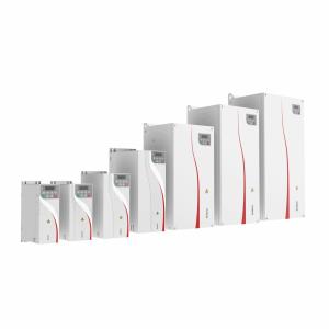
- Book-type design greatly saves the installation space in the user’s cabinet
Professional thermal design
- Adopt efficient and accurate thermal simulation platform software to ensure the thermal reliability of the entire machine
- Advanced thermal testing and verification technologies and devices effectively test the theoretical results of thermal design
Rigorous temperature rise test
- The whole machine temperature rise test adopts strict full load and overload verification test procedures
- Ex-factory high temperature and load aging, effectively preventing and intercepting scattered device failures
Effective anti-interference design
- Built-in C3 filter, which can effectively suppress high-frequency harmonics generated by the inverter
- EMC ground-breaking design can effectively reduce leakage current to the ground
Comprehensive protection features
- The entire series has protection functions such as over-voltage, under-voltage, over-current, phase loss, over-speed, blocked rotor, overload, motor temperature protection, and short circuit to ground.
- According to the severity of the fault type, it can be set to early warning prompt, fault shutdown and continued operation to facilitate daily maintenance.
Excellent performance
Advanced motor drive technology
- Can support asynchronous motors and synchronous motors to achieve high-performance current vector control
- Can support two sets of motor parameter switching control
- Can support motor speed and torque mode control
Rich self-learning functions
- Accurate motor parameter self-identification ability to improve motor control accuracy and response speed
- Diverse and comprehensive self-learning modes to support motor identification needs in different scenarios
Perfect braking function
- Support start and stop DC braking function
- Over-excitation function can effectively suppress the rise of bus voltage during deceleration and avoid frequent over-voltage faults.
- All series can have built-in braking units, saving installation space and electrical costs
Powerful overload capability
- High overload capacity, capable of reliable operation for a long time under extreme load conditions
- Light overload capacity: 1.1 times rated current operation for 1 minute, 1.5 times rated current operation for 10 seconds
- Heavy overload capacity: 1.5 times rated current operation for 1 minute, 2 times rated current operation for 3 seconds
Rich functions
Diversified extended functions
- Communication card option, supporting various current mainstream communication protocols: Profibus-DP, Profinet IO, CANopen, Modbus TCP/IP, Ethercat, EtherNet/IP, etc.
- Encoder card option, supports incremental and resolver encoder wiring
- I/O terminal card option makes terminal functions richer
- External keyboard option makes debugging easier and easier
Note: The optional I/O terminal expansion card and communication expansion card are in the same expansion card slot, and they cannot be installed and used at the same time
Background quick debugging software
- Supports inverter event recording and virtual oscilloscope functions
- Support parameter editing and status monitoring, making debugging and maintenance more convenient
High frequency output
- The output can reach up to 1500Hz, suitable for high frequency and high speed motors
Featured application software functions
- Master-slave control: suitable for master-slave synchronous control of 2 or more motors
- Simple PLC function: can complete up to 16-segment timing and fixed-speed cycle operation
- PID function: suitable for closed-loop systems for process control such as constant temperature, constant pressure, tension, etc.
- Virtual I/O: Simple internal logic control can be achieved through simple settings
- Power outage and restart function: When the inverter is powered off and on again during operation, automatic operation can be realized
- Multi-motor switching function: can store two sets of motor parameters to achieve switching control
- Zero servo function: During closed-loop control, the motor can be locked at zero speed to achieve a zero-speed hovering effect.
- Swing frequency function: suitable for textile and chemical fiber processing equipment, which can improve the quality of spindle winding
- Random PWM depth: can improve the harsh noise of the motor
- Encoder redundant operation: suitable for closed-loop operation. When the encoder fails, it can automatically switch to open-loop operation.